Ortho wireframe
Ortho filled
Persp wireframe
Persp filled
The Main Window is where you modify a model. The Main Window has a menu bar, a tool bar, a status bar, and a number of viewports that let you see the model from various directions. There are also several dockable windows. The Properties Panel in particular can be very useful.
There are two modes for the main window. The default one is the Model Edit Mode. This is the mode you are in when you start Maverick Model 3D and are viewing a model. In this mode changes you make affect the position of polygons and bone joints. The other mode is Animation Mode. This mode is active when you have the Animation Panel open. In this mode changes you make affect the current animation frame.
The Tool Bar has a set of tool buttons. The tools allow you to manipulate a model interactively. For example, you can select the "Draw Cube" tool and then click and drag the mouse in a viewport to create a cube. Each of the tools in the toolbar is also available in the Main Window's Tools menu.
The menu bar has several menus that provide other functions to modify or create a model.
The File menu allows you to open and save models. There is also an export option to allow you to save in experimental formats. If the file format you want to save as does not appear in the "Save As" dialog, try the Export function. The most recent files you have opened or saved are listed in the "Recent Models" menu. You can load one of these models by selecting the filename from that menu. Additionally, the File menu also allows you to view available plugins.
The View menu allows you to change the number and layout of the viewports in the view window (you may have 1, 2, 4, 6, or 9 viewports). You can force the viewports to show the whole model or selected region by selecing either the Frame All or Frame Selected options, respectively. You can select how to display the model in the othographic (canvas) and perspective viewports based on four options.
There are also some rendering options in the Render Options View submenu. These options include how bone joints are displayed, whether or not texture projections objects are visible, how missing textures are rendered, whether polygon edges (3d lines) are displayed in the perspective views, and whether or not back-facing polygons are drawn.
You can choose how you want bone joints to be displayed. Bones draw a diamond-like object that is thicker toward the parent joint and thinner near the child joint. The Lines option just draws one line between each parent and child joint. The hidden option disables drawing of bone joints.
The Error Texture options indicate how you want unloadable textures to be displayed. The Red Error Texture is a black 'X' on a red background. It is designed to be an obvious indication that textures are missing. If you do not care about missing textures you can use the Blank Error Texture which will render missing textures as if the mesh had no texture applied (material lighting properties will still apply).
The Render/Hide 3D Lines option is used to enable/disable drawing of lines in the perspective viewports. This can be useful if you want to see selected edges in the perspective viewport.
The Draw/Hide back-facing triangles option is used to enable/disable drawing of triangles that are facing away from the viewport camera. By default these are rendered as darkened polygons. In some cases you may want to these polygons to be invisible if they are not facing the camera (such as when using transparent textures).
The Tools menu lists all the available tools. The options in this menu are also listed in the toolbar.
The Model menu has features that affect the model as a whole or large portions of the geometry. It also includes the Undo and Redo options.
Edit Model Meta Data allows you to attach user-defined text values to the model as key/value pairs. In general these have no influence on the model or its geometry, the are just a place for you to store arbitrary information (such as author/artist information, copyright, URLs, etc.).
Transform Model allows you to apply a transformation Matrix to the model. It opens a tab window with different types of transformations. There are tabs for translation, rotation, and scaling, as well as a tab for a user-defined matrix. In some cases the Matrix you want to apply may not be undo-able. If this is the case, the program will warn you before performing the transformation. See the Transform Model Window for more details.
Boolean Operation allows you to combine two object into one. See the Boolean Operation Window for more details.
Set Background Image adds a background image to one or more of the six pre-defined orthographic projections. Background images can be useful as a modeling reference when attempting to create complex shapes. See the modeling tutorial for more information.
Merge imports the geometry, materials, and animations from another model file into the current model. See the Merge Window documentation for details.
Import Animations imports the animations from another model file into the current model. The skeletons of the two models must match.
The Geometry menu lists non-interactive operations that modify model geometry.
The Materials menu lists non-interactive operations that modify groups and materials. See Material Details for more information.
The Influences menu includes functionality for dealing with bone joints and how they influence the model geometry. See the Influences Menu and Bone Joint Details for more information.
The Animations menu provides functions to manipulate model animations. There are interactive and non-interactive functions provided by this menu. See the Animation Panel and Animation Details for more information.
The Help menu brings you to this documentation.
The status bar contains text (on the left side) that describes the results of recent operations on the model. On the right side it shows you how many vertices, faces, groups, bone joints, points, and materials exist in the current model. If you have any vertices, faces, bone joints, or points selected the count will be shown with the selected separated from the total with a slash ('/').
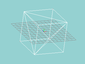
The Viewports in the center of the Main Window are where you view and modify a model. There are two types of viewport views: Perspective Views and Orthographic Views. In this documentation orthographic views are sometimes called canvas views because those are the views in which you can use tools to change the model (like a drawing canvas in a 2D paint program). The view type and direction is indicated in a combo box above the viewport on the left. The field of view is indicated in a text entry box above the viewport to the right of the view direction. Larger numbers mean you can see more of the model canvas (think of the opposite of zoom). Three short colored lines indicate the origin. Each color extends in the positive direction along an axis. The red line extends along the X axis, the green line extends along the Y axis, and the blue line extends along the Z axis.
|
Ortho wireframe |
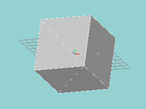
Ortho filled |
|
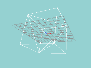
Persp wireframe |
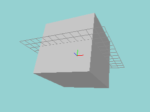
Persp filled |
You can scroll the active viewport by clicking on the arrows in the upper-right corner. The four-way arrow allows you to click and drag the viewport. You can also use the middle mouse button to drag the viewport. You can zoom in and out by using the magnifying glass buttons above the viewport scroll buttons.
Holding the Ctrl key and clicking on the pan arrows in the corner will rotate the viewport. Holding Ctrl and using the mouse scroll wheel will also rotate the viewport.
The view type and direction can be changed to see the model from various angles. In the Perspective View near portions of the model appear larger, far portions of the model appear smaller. The Perspective View may also have visible lighting and texture effects. This view only allows you to view the model. You cannot modify the model from a viewport in Perspective mode.
By left-clicking and dragging your mouse pointer you can rotate the perspective view along the horizontal axis or vertical axis. By middle-clicking and dragging you can pan the viewport left, right, up, and down. Using the scroll wheel will zoom in or out. The right mouse button has no effect in the Perspective View.
The Orthographic Views show the model from one of six directions: Front, Back, Left, Right, Top, or Bottom. These views are a CAD-like projection of the model from the specified direction. These views are not modified by perspective. Two cubes of equal size will always appear the same size in this view regardless of how "far" they are from the viewing plane. Each of the six orthographic views is a canvas view, where you can create and manipulate model vertices and faces. The othrographic viewports may also render the model as a wireframe, solid-flat polygons, solid-smooth polygons, or textured polygons.
An orthographic viewport can be rotated by holding the Ctrl button and click-dragging with the left mouse button. You can toggle a viewport between orthographic and perspective by pressing the Left Quote (Backtick) key.
If you want to be able to save your current viewport settings (pan, zoom, and rotation) and restore the settings at a later time, you can press Ctrll+[Num] where [Num] is a number key from 0 to 9. To restore the viewport, press the [Num] key.
The effect of the left and right mouse buttons depends on the tool that is currently selected. The left mouse button is the main tool button and the right button is an alternate button. For example, using the select tool you can select vertices and faces with the left mouse button and unselect them with the right mouse button. By middle-clicking and dragging you can drag the viewport left, right, up, and down. Using the scroll wheel will zoom in or out.
The active viewport (the viewport under the mouse) will have a slightly lighter background color than the others. Some keyboard shortcuts will modify the selected viewport. For example + and - will zoom in and out. 0 (zero) will center the viewport on the origin. The backslash will flip an orthographic view to the opposite side (front view will become a back view). The backtick (left quote) will switch an orthographic view to a perspective view.