


There are seven Select tools that allow you to select vertices, faces, connected meshes, groups, bone joints, points, and texture projections. Each behaves in a similar manner as described below.
The Toolbar has a set of tool buttons. The tool buttons represent tools that allow you to manipulate a model interactively. For example, you can select the "Create Cube" tool and then click and drag the mouse in a viewport on the Main Window to create a cube.
There are two types of tools in the toolbar: Creation tools and manipulation tools. Creation tools create new vertices, faces, and joints interactively in various shapes such as cubes and spheres. Manipulation tools allow you to interactively change faces, vertices, and joints which already exist. Manipulation tools include moving, scaling, and rotation tools. Typically manipulation tools only operate on vertices, faces, or joints which have been selected with the "Select" tool.
It is important to note that faces often share vertices. Unselected faces may be modified by changes to vertices which are also part of a selected face. To disconnect faces from each other so that they do not share vertices, see the Unweld vertices command.
Some tools have additional options, which appear in an a separate toolbar. For example, the sphere tool has an option that specifies how many triangles the sphere will be composed of.
The tools menu contains a "Snap To" submenu. In this submenu there are two options: "Snap to Grid" and "Snap to Vertex". The former will cause objects dragged by the mouse to align with the nearest grid line when it comes close enough. The latter will cause the objects to align with the nearest vertex.
There are seven Select tools that allow you to select vertices,
faces, connected meshes, groups, bone joints, points, and texture
projections. Each behaves in a similar manner as described below.
Click and drag in a canvas viewport with the left mouse button. This will create a bouding box. When you release the mouse button all objects of the desired type (vertices, faces, groups, or joints) that are within the bouding box will be selected. In the case of faces or groups, the entire face or group does not need to be within the bouding box. If any portion of the object is within the bouding box it will be selected.
Each time you press the left mouse button you begin a new selection. If you want the selection to be cumulative, you may hold a shift key down to prevent the tool from unselecting vertices. Using the shift key in this way you may select multiple objects by repeatedly using the left mouse button.
The right mouse button is used to unselect objects. You do not need to hold the shift key down to prevent clearing all of the current selection. This is implicit when using the right mouse button.
The select faces tool has an option to select back-facing faces. If checked, any faces in the selected region will be selected (this is the default behavior). If unchecked, only faces that are facing the camera in the selected region will be selected.
The select tools operate the same way in animation mode as they do in model edit mode; however, some animation types do not allow you to select some objects. For example, in skeletal animation mode you can only manipulate bone joints.

The Move tool moves selected vertices and faces.
Press and hold the left or right mouse button in a canvas view to begin a move operation. Drag the mouse with a button down to move selected vertices or faces in a canvas view.
You can force the move tool to only move in one dimension by holding the shift key. The first dimension the tool detects movement on will be the only dimension you can move the selected primitives in.
In animation mode the move tool moves vertices or bone joints. The move tool may have no effect on certain types of animations. In skeletal animations, moving a bone joint will set a translation keyframe for the current frame of the current animation. For frame animations, moving vertices will set the vertex position for the current frame of the current animation.

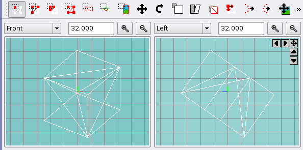
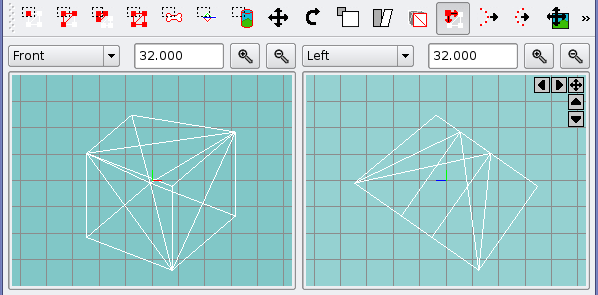
The Rotate tool rotates selected vertices and faces around a point.
Press and hold the left mouse button in a canvas view to begin a rotate operation. Drag the mouse around the rotation point (default rotation point is the center of the seleced object, but this can be changed with the right mouse button).
Hold the shift button to rotate selected vertices in 15 degree increments. This can be useful if you want to rotate something by an exact amount (like 15, 30, 45, 90, or 180 degrees.
The right mouse button sets the rotation point in the canvas view. The rotation point is indicated by a green crosshair.
In animation mode the rotate tool rotates vertices for frame animations and sets rotation keyframes for bone joints in skeletal animations. The rotation of vertices is identical to the operation in model edit mode. The rotation of bone joints is different from model edit mode in that the rotation is always centered on the bone joint.

Scale selected vertices and faces.
Press and hold a mouse button to begin a scale operation.
You can specify whether to scale from the far corner of the selected mesh or the center of the selected mesh by changing the Point combo box in the toolbar. By default the center point is used.
The amount of scaling is based on the position of the mouse relative to the scaling point, and the position of each selected vertex (vertices farther from the scaling point will scale more than vertices closer to the scaling point).
You can force the scale tool to preserve the aspect ratio of the scaled object in 2 or 3 dimensions using the combo box in the toolbar. By default the aspect ratio is not preserved.
You can force the scale tool to only scale in one dimension by holding the shift key. The first dimension the tool detects movement on will be the only one scaled. The shift key is ignored if you are preserving the aspect ratio through the combo box (input will only be counted on in one dimension, but 2 or 3 will be scaled by that input).
In animation mode the scale tool scales vertices for frame animations. It has no effect on skeletal animations.

Shear selected vertices and faces.
Press and hold a mouse button to begin a shear operation. The shear tool will find the bounds of the selected vertices. The nearest edge of the bounding region will be dragged in the direction of mouse movements. For example if the nearest bounding edge is the top edge, the top edge will move left or right while the bottom edge will remain stationary.
Horizontal edges move left or right. Vertical edges move up or down. Vertices between the moving edge and anchored edge will move proportionally based on their relative position between the two edges.
In animation mode the shear tool shears vertices for frame animations. It has no effect on skeletal animations.

Extrude selected faces. This works like the extrude tool except
that instead of entering a numeric offset for the location of the
extruded faces, you drag the faces to the desired location with the
mouse.
Press and hold a mouse button to begin an extrude operation. The faces you select will move with the mouse. New faces will be created to connect the moving faces to the rest of the object. If you release the mouse button and press and hold again, it will start a new extrude operation.
This tool works like a create tool and has no effect in animation mode.

Drag Vertex on Edge of a triangle toward connected vertices.
Press and hold a mouse button to begin a drag operation. As you move the vertex it will follow the closest edge of a triangle that the vertex belongs to.
Before
After
In animation mode the drag vertex tool moves vertices for frame animations. It has no effect on skeletal animations.

Attract Near translates selected vertices. Vertices closer to the mouse are affected
more by the translation than far vertices.
Press and hold a mouse button to begin an attract near operation. Drag the mouse to move the selected vertices. The nearest vertices will move the most. The farthest vertices will not move at all.
In animation mode the attract near tool moves vertices for frame animations. It has no effect on skeletal animations.

Attract Far translates selected vertices. Vertices farther from the mouse are affected
more by the translation than near vertices.
Press and hold a mouse button to begin an attract far operation. Drag the mouse to move the selected vertices. The farthest vertices will move the most. The nearest vertices will not move at all.
In animation mode the attract near tool moves vertices for frame animations. It has no effect on skeletal animations.

The Move Background Image tool moves the center point of a
canvas background image.
To set a background image for a viewport, use the Select Background Image Window.
Press and hold a mouse button to drag the image to the desired position.

The Scale Background Image tool increases or decreases the size of the
canvas background image.
Press and hold a mouse button to scale the image size up or down. Moving closer to the center will make the image smaller. Moving away from the center will make the image larger.
It is not possible to scale the X and Y dimensions independently.
To set a background image for a viewport, use the Select Background Image Window.

The Create Rectangle tool creates two triangular faces that form a
rectangle.
Press and hold a mouse button to begin creating a rectangle. The first corner of the rectangle will be located at the point of the mouse button press. Move the mouse to the location of the far corner and release the mouse button to finish creating the rectangle.
Create tools have no effect in animation mode.

The Create Vertex tool creates a vertex that is not connected
to any triangles.
Normally vertices that are created when triangles are created will also be deleted when triangles are deleted. A vertex created with the Create Vertex tool is a "Free Vertex". You can create a triangle connected to this vertex then delete the triangle later and the vertex will still be present. A "Free Vertex" will only be deleted if it is selected explicitly and deleted.
Press a mouse button to create a vertex. If you hold the button down you can move the new vertex until the button is released.
Create tools have no effect in animation mode.

The Create Cube tool creates a set of faces in the shape of a cube.
When you select the create cube tool the cube tool bar will appear. You can use the cube tool bar to force the new cube to be cube shaped (the same width, height, and depth). You can also increase the number of faces that make up the cube by changing the value of segments. The segment value is N for an N by N by N cube. So a segment value of 3 would give you nine sets of squares (3x3) on each cube face (9 squares, 18 faces).
Press and hold a mouse button to begin creating a cube. The first corner of the cube will be located at the point of the mouse button press. Move the mouse to the location of the far corner and release the mouse button to finish creating the cube.
The cube will be as deep as its narrowest side.
Create tools have no effect in animation mode.

The Create Ellipsoid tool creates a set of faces in the shape of
an ellipsoid. The depth dimension of the tool will be identical to the
shorter of the two radii (an ellipse is cigar-shaped, not plate-shaped).
When you select the ellipsoid tool the ellipsoid tool bar will appear. You can use the ellipsoid tool bar to increase the smoothness of the ellipsoid or make the ellipse a sphere (forcing the the radii to be the same in all three dimensions).
Press and hold a mouse button to begin creating an ellipsoid. The ellipsoid will be drawn within the space you drag the mouse over, or with the center at the original click point, depending on the value of the From center check box in the tool bar. Release the mouse button to finish creating the ellipsoid.
Create tools have no effect in animation mode.

The Create Cylinder tool creates a set of faces in the shape of a cylinder.
The cylinder is always drawn "horizontally" in the canvas view.
The "width" is the length of the cylinder and the "height"
is the diameter of the cylinder. Cylinders may be solid or hollow and may
taper at one end.
When you select the cylinder tool the cylinder tool bar will appear. You can use the cylinder tool bar to increase the the number of segments (lengthwise) of the cylinder by setting the segments spin box. You can increase the the number of sides (around the cylinder) of the cylinder by setting the sides spin box. You can make a cylinder hollow by using the width spin box. The width is how think the cylinder is (as a percent of the radius). 100 is solid and 0 is an extremely thin cylinder. The scale is the size of one end of the cylinder relative to the other as a percentage of the total diameter. 100 is a cylinder, 0 is a cone with one pointed end.
Press and hold a mouse button to begin creating a cylinder. The diameter of the cylinder will be the "height" (vertical distance) in the current canvas view. If the cylinder is cone-shaped, the smaller end will be where the drag began. Cylinders are always "horizontal" in the current viewport. You can use the rotate tool to change the orientation of a cylinder that has been created (holding down shift during rotation will allow you to rotate in 15 degree increments).
Create tools have no effect in animation mode.

The Create Torus tool creates a set of faces in the shape of a torus.
The torus is always drawn with the "hole" visible in the canvas view
where the torus was created. You can increase the polygon count of the
torus by changing the "smooth" value.
When you select the torus tool the torus tool bar will appear.
The width is width of the cylindrical portion wrapped around the center. 50 means the cylinder spans from the far outside of the torus to halfway to the middle of the torus. 100 means the cylinder spans all the way to the center of the torus. 199 means the torus will be almost spherical.
You can check the circle checkbox to force the torus to be circular.
Press and hold a mouse button to begin creating a torus.
Create tools have no effect in animation mode.

The Create Polygon tool creates a triangle strip or fan.
Each left click will create a new vertex for the polygon.
When you select the polygon tool the polygon tool bar will appear.
If the fan checkbox is checked the polygon will be a triangle fan. If the checkbox is unchecked, the polygon will be a triangle strip.
You can check the circle checkbox to force the torus to be circular.
Press the left mouse button to create each vertex of the polygon. Press the right mouse button to invert the normals of the most recently created polygon.
Create tools have no effect in animation mode.

The Create Bone Joint tool creates a bone joint connected to the nearest bone
joint.
Press a mouse button to create a bone joint. Hold the button down to move the joint where you want it. If there are no other joints the first joint you create will be a root joint. If there are other joints, the new joint will be connected to the closest existing joint (the existing joint will be the "parent" of the new joint).
The closest joint is the closest joint in the two dimensions of the orthographic canvas view you are creating the bone joint in. The third dimension (the depth) is not included in the distance calculation.
If you want the joint to be connected to a joint other than the closest one to the place where the joint will be positioned, create it near the parent joint and drag it to its target location.
Create tools have no effect in animation mode.

The Create Point tool creates a point. Points have a position and a
direction. Points do not have a specific purpose for MM3D. They can be used
as bolt points or other custom-purpose tags for model exporters or game
engines. For example, the MD3 filter looks for specially named points to
act as MD3 "tags".
You can use the rotate tool to rotate a point into a new direction, or explicitly set the rotation using the Rotation Properties Panel.
Points can be assigned to bone joints in the same manner as vertices.
Press a mouse button to create a point. Hold the button down to move the point where you want it.
Create tools have no effect in animation mode.

The Create Texture Projection tool creates an object to project a texture
onto faces as a sphere or cylinder. Texture Projections have a position and a
rotation. Texture projections do not have a texture associated with them.
The texture applied to faces is the texture assigned to the group to which the
faces belong (in theory you could use the same texture projection to map two
different textures onto two different sets of polygons).
You can change the type of projection to create by selecting the type from the Type combo box. You can also change the type of a projection after creating it using either the Texture Projections Window or the Projection Properties Panel.
Any faces that are selected when you create the projection will automatically be assigned to the projection.
Press a mouse button to create a texture projection. Hold the button down to scale and rotate the projection to the size and orientation that you desire.
Create tools have no effect in animation mode.